A New Idea for Video Game Dialogues
I have been interested in the creation of tools for making video games, especially dialogue systems, for a while now. In this post I want to showcase a proof-of-concept for a new dialogue system, which I believe to have some potential and probably also some flaws. Consider this a postmortem of a system I am not using anyway.
If you are interested in systems and a bit of programming language theory this post might be for you.
Previous Post Recap
In a previous post about video game dialogues I talked about an idea for a new system for structuring such dialogues to make them feel more natural without causing a combinatorial explosion in the choices you have to provide. To recap, my main idea was to structure the nodes in dialogues as polytrees. By “nodes” I mean the single segments of the dialogue. Edges in such a graph would represent conditionals or side-effect free operations, allowing to specify complex logic to be evaluated during the graph’s traversal. A dialogue would look something like this:
Importantly, it allows multiple start and end nodes and arbitrary merging of dialogue paths into a common path. Additionally, loops in the graph are forbidden! As we will see later, this is a fundamentally important property of this new system that allows us to make reasoning about the user experience much easier and also allows for static analysis of the system.
While fleshing out this idea, I worked on a proof-of-concept dialogue editor for this system which gave me much more insight into how to set it up. This post is an exploration of this prototype, what works about this system, what could be improved and what cool stuff might be possible when working a bit more on it. You can think of it as a postmortem of the proof-of-concept implementation.
The Implementation Idea
After surveying other dialogue editors and systems that are out there I quickly came to the conclusion, that I would need some kind of graph-based UI to represent the branching dialogues. My design decisions were heavily influenced by this GDC talk by Carrie Patel and David Szymczyk, especially by the debugging and analysis capabilities of the system they showcased.
I also tried out solutions without a graph-based UI, but they felt a bit too confusing to me once the dialogue had grown to a certain size. After learning that some commercial solutions also go the “graph route”, I was convinced.
However, a major problem that I saw with other systems is that dealing with data always seemed to be poorly integrated. The writer of a dialogue has to use complicated naming schemes for global variables, manage data through convoluted tables and/or generally deal a lot with IDs.1
To combat this problem, my idea is to mix information on the sequence of events in the graph with information on data dependencies. This is achieved by essentially drawing two graphs at once, sharing the same nodes, but with disjunct edges in different directions. The timeline (the sequence of events) flows into one direction while the data dependencies flow in the other direction. This will make sense once examples are discussed.
Design Goals
Some goals I tried to achieve:
- Easy and fast editing: The experience should be as non-technical as possible. Writing the dialogue should feel like writing, not like programming. It should be easy to make changes even in dialogue with complex branches.
- Engine/Framework independence: The editor and its output should be completely independent of any game-engine or framework. The dialogue should be stored in some ubiquitous format.
- Game logic independence: The dialogue should be completely separated from the game’s logic. While it should be possible for the game to react to events in the dialogue, it should not be able to interrupt the dialogue and cause unforeseen behavior.
- Testability/Readability: Dialogues should be easy to read. Conditions and branching should be obvious. Nothing should be hidden in submenus. Dialogues should be testable from within the editor.
- Minimal named variables / identifiers: When dealing with data, the amount of explicit names or IDs that need to be given for variables and values should be kept to an absolute minimum. Data should be anonymous and implied by the dialogue’s structure.
- Support for complex branching and conditions: It should be straight forward to create complex branching behavior based on the handled data.
Data-aware Dialogues
The new system I call “Data-aware Dialogues” is completely agnostic about the game (or application) it is running in. It is more of a specification than an actual implementation. The idea is that an editor is used to construct, test and statically verify the dialogue which is then exported in some intermediate format (in this case it’s JSON). This format has to be interpreted by the game, which makes this system portable and completely agnostic to any game-engine or framework and also makes it possible to check in these resources into version control.
Basic Makeup of a Dialogue
In this new system, a dialogue is seen as a simple function that receives a start label and input variables and returns an end label and output variables.
The labels are used to signify which start node should be taken and which end node was reached. Variables are a flat collection of key-value pairs that map string keys to either boolean, integer or string values. The keys in these maps are statically known, so they essentially act as an interface between the dialogue and the game, the dialogue is embedded in. Note that these maps could be empty, if such data is not needed.
Since the game is tasked with storing these maps and making sense of the data in between dialogues, there is a clear distinction between logic in the dialogue and logic in the game. Logic and data is completely separated from both domains. While this might seem like a restriction, it makes it possible for the writer to create and test the dialogue without ever touching the codebase of the game. There are no test builds to create. Everything can be done inside the editor.
The Graph-based Editor
The editor prototype is implemented using the open-source Godot engine. This allows the editor to be embedded into the Godot editor as a plugin or be used as a cross-platform standalone application. Even a web-app export is possible.
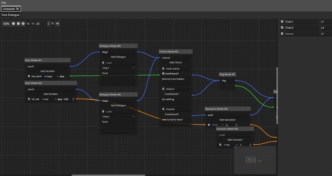
The graph-based UI is implemented using the powerful GraphNode component inside the engine. On the left-hand side, a list of characters known to the dialogue (as well as their IDs) is given. In a real implementation this should be handled differently, as names are currently hard-coded.
Since most of the functionality lies within dialogue graph, let us focus on it. We can see a bunch of nodes, to be discussed later, which are connected with edges of different colors. Nodes have their inputs on the left and outputs on the right. The main idea is that blue edges are used to designate the timeline of the dialogue, meaning the sequence of nodes to be visited, while other nodes designate data-dependencies between nodes. We call these timeline edges and dependency edges. Timeline edges are read left-to-right and dependency edges are read right-to-left. Dependency edges have different colors for the different types of values, green for booleans, orange for integers and brown for strings. We will also call the connection points for edges timeline connections and dependency connections respectively. Note that nodes, with multiple outgoing timeline edges indicate some sort of choice. The exact meaning of that will be clear once we discuss the different dialogue nodes.
Only one timeline edge can be connected to an outgoing connection, but multiple can be connected to an ingoing connection. It is the exact opposite for dependency edges. In order to understand why, we need to discuss the interpretation of dialogues.
Interpretation of the Dialogue
Let’s firstly focus on the timeline edges. They specify the sequence of nodes to be visited. Some nodes can have multiple outgoing timeline connections. Here is an example.
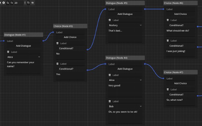
However, only one of these connections can be taken and the internal logic of the nodes makes sure of that. There can only be a single timeline edge connected to an output connection, otherwise the sequence of nodes in the dialogue would be non-deterministic. The editor makes sure that this is the case.
Dialogues start with a start node and end in an end node, which are discussed later. Since the timeline edges are deterministic (the next edge to take is always clear) and loops are disallowed, we know that an end node will be reached if all paths end in such a node. These properties have to be checked by the editor; the interpreter can therefore assume that these properties hold.
Dependency edges, as mentioned before, are not read left-to-right but right-to-left. That’s because they specify a dependency on some data, which is evaluated when a node with an ingoing dependency connection is evaluated. These nodes rely on the data to be present for their internal logic, so the interpreter now needs to backtrack the dependency connections. Here is an example.
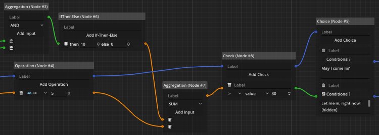
The last node, has an ingoing dependency edge to the check node. As this node also has their own ingoing dependency connection, it also has to be followed. In the interpretation, the dependency edges are being followed until we find a node that provides an outgoing dependency connection without relying on an ingoing dependency connection. In programming terms, this can be understood as a “call-by-need” evaluation strategy. Since the data from a dependency connection has to be unique, an ingoing dependency connection can only ever have a single edge, while an outgoing dependency connection can have as many edges as needed. Just as with timeline edges, loops are disallowed.
An important concept about dependency edges is that they are typed. It’s not possible to connect a green edge (designated for booleans) to an orange connection (designated for integers). The point of this color-system is that writers with no programming knowledge should still be able to literally see what kinds of data are expected and that you cannot just use an integer and interpret it as a boolean without specifying how to.
One last thing about nodes: All nodes have labels and some of them have even more sub labels for their elements. These labels are used for debugging and asynchronous communication with the game. Only labels for start and end nodes have a special meaning as they are used to select the correct start node for the dialogue and also communicate to the game which end node was reached.
Overview of Dialogue Nodes
Let’s go through the nodes implemented in the prototype. I believe the set presented here is sufficient in order to create engaging and interesting dialogues.
Start and End
The only necessary nodes in the dialogue are start and end nodes. They designate the start and end of the dialogue.
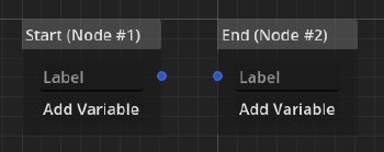
Each of them can carry a label, which ideally should be set to a unique value. This allows the game to choose different start labels and be presented with different end labels based on the timeline. The writer can thus create different versions of a dialogue (e.g. “first visit”, “second visit”) and also communicate what happened within the dialogue (e.g. “good ending”, “bad ending”) to the game.
An important feature of these nodes are their input, which are the aforementioned key-value pairs. In order to allow easier integration, default values are given for the keys.
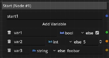
In this example, we have three variables var1, var2 and var3 of the type bool, int and string with the default values true (given by the check button), 5 and foobar respectively.
The exact same interface is provided for end nodes.
However, the meaning of the default values is dependent on the underlying node type.
For start nodes the default values is used when no value under the given key was found.
For end nodes it means that if two end nodes specify different sets of keys, the output of the dialogue will still contain the union of all keys for end nodes.
The keys not present in the reached end node will be filled with default values.
I haven’t decided what should happen when end-nodes don’t agree on their default values. It seems to me that there should be some kind of different system to handle this. Some values should be required, but that makes interfacing with the dialogue system a bit harder.
Dialogue
The single most important (but arguably most boring) node is the dialogue node. It is used to specify a bunch of text with associated characters.
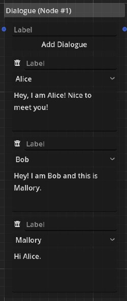
In this example we have three characters speaking one after the other. Whether the player needs to press a “continue” button or the text is just displayed like that is left to the game’s interpretation of the dialogue node.
Having multiple spoken passages in one node is a simplification of having multiple dialogue nodes in sequence. The following configuration is equivalent to the first example.

Within a dialogue node there is no choice to be made, therefore the node has one ingoing and one outgoing timeline connection. The node is also not concerned with data, so there are no ingoing or outgoing dependency connections.
Choice
Another crucial piece of the toolkit is the choice node, which allows the player to make choices.
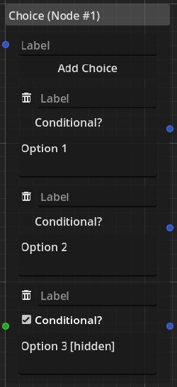
The node in this example presents three choices which would prompt the player with “Option 1”, “Option 2” and “Option 3 [hidden]”.
There is exactly one ingoing timeline connection and one outgoing connection for each of the choices.
Choices can also be conditional.
In that case, the choice has an ingoing dependence connection of type bool which has to evaluate to true for the choice to be shown.
So in our example, the ingoing dependence connection would need to evaluate to true for “Option 3 [hidden]” to be displayed, while the other choices are always displayed.
Switch
A similar node to the choice is the switch node. It chooses a different timeline connection based on the incoming dependence connections.
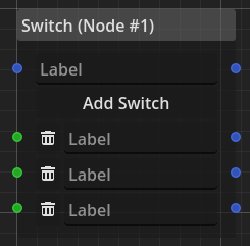
Based on the ingoing dependence connections of type bool a different timeline connection is being selected.
The ingoing dependence connections are checked from top to bottom and the first one that evaluates to true is taken.
Note that there is one default timeline connection at the very top which is being used if none of the ingoing dependence connections evaluate to true.
Therefore, the dialogue cannot get stuck on this node.
In programming terms, this is a if-then-else block.
Flag
In order to mark that a certain point in the timeline has been reached, we can use the simple flag node.
It has timeline connections and a single dependency connection for a bool value.
This value evaluates to true if the node has been reached in the timeline.
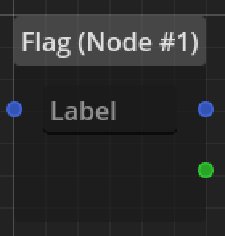
It is by far the simplest node, but it is powerful, as it visually shows the dependence on events in the timeline. To illustrate this let’s look at an example.
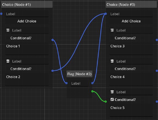
We can see that “Choice 5” will only ever be shown if “Choice 1” was taken before, even though both “Choice 1” and “Choice 2” point to the exact same node. Using this node, we can remember events in the timeline. Let’s say that a choice made the player tell another character a secret. The flag would now be a stand-in for the secret to be known to this character (and could be labeled as such!).
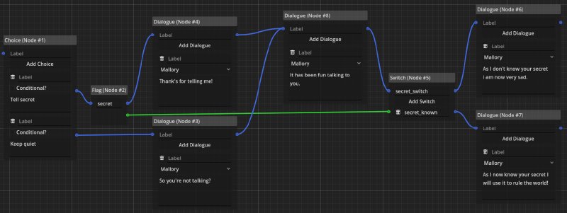
In the example above, we can see this behavior modeled. The flag and switch nodes are needed to make a distinction after the timelines have been merged into the common dialogue node. We can see visually where the information for the switch in the dialogue is coming from. We don’t need to inspect some global variables or even think about how to manage them. This is all taken care of, which might make the flag node, the most useful in the whole system.
Constant
A constant node is used to provide constant values for dependencies to the dialogue.
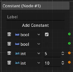
Note that these are not named variables. The outgoing dependency connections simply provide constants upon evaluation. In the backtracking procedure discussed before, this node (together with start nodes) is the source for data. So all paths in the polytree induced by the dependency edges have to either start at a constant or start node.
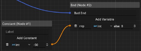
This example provides the output variable rep with the value -50 if this end node is reached at the end of the dialogue.
Operation
Since only having static values in the dialogue is no fun, there is the operation node which builds a bridge between the timeline and data dependencies.
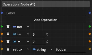
This node supports four operations:
- not: Boolean negation
- +=: Adds a constant value to an
intvalue - -=: Subtracts a constant value from an
intvalue - set to: Sets a value of specified type to a value of that type
It would be simple to add more operations on booleans and integers, but for the prototype I restricted myself to the ones I felt are most useful.
The interpretation of this node is not as straightforward as the other ones we have seen so far. Whether a data-dependency is affected by the specified operations is dependent on whether this node was reached in the timeline. Let’s look at an example, to make its usage clear.

In the example above, a start node provides the variables x and bool.
The x variable is connected to two operation nodes, one of them adding the value 5 to it and the other adding 10.
A switch node is being used to branch the timeline based on the value of bool.
If bool is true, the timeline will continue at the operation node adding 10, otherwise it will continue at the other operation node.
Both end in their own respective end nodes, which both name their modified int values as y.
This dialogue is essentially a very simple function:
This already shows us the data-aware part of the dialogue system. It is possible (and indeed a design goal) to simulate non-recursive mathematical functions using the nodes presented here. The connection of data-dependencies and the timeline is the key ingredient here. Based on choices the player makes (using choice nodes) we can completely change the data-flow of the dialogue, all the while we do not have to deal with variable names or a complicated database of rules.
Check and If-then-else
The check node is used to convert an int value to a bool value using a comparison.
Conversely, the if-then-else node is used to turn a bool into an int value.
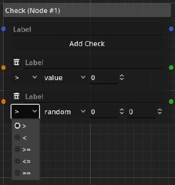
Comparisons can be made using a constant value or a random value with a specified range (minimum and maximum).
The if-them-else node is even simpler and doesn’t really need any explanation.
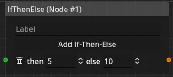
In combination these two nodes allow for conversions between bool and int values which is needed to turn flags into numeric values and numeric values into flags.
This can be used to model skill checks.
One might ask why the check node needs timeline connections and indeed this is not yet finalized. My idea was to allow the game to respond to this check at a specific point in time to play an animation or a sound and respond to the “check event”. Many role-playing games have this mechanic where they show a “check succeeded” or “check failed” message and this is what I wanted to model. Since data-dependencies are only evaluated when needed, the checks need to show up in the timeline. However, this makes things messy as these nodes don’t strictly need to have a timeline connection.
Aggregation
In order to combine boolean conditions and to calculate integer values from other values, the aggregation node features a number of operations to aggregate multiple inputs into a single output.
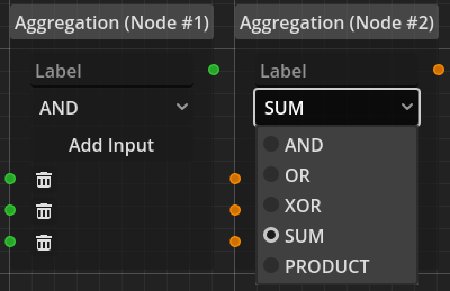
In this example we see a node computing the conjunction of three bool inputs and a second node computing the sum of three int inputs.
The operations supported are:
- AND: Conjunction of
boolinputs - OR: Disjunction of
boolinputs - XOR: Exclusive-Or applied to
boolinputs - SUM: Sum of
intinputs - PRODUCT: Product of
intinputs
The number of inputs is completely variable. Note that using constant nodes, we can also model the not, += and -= operations from the operation node, without the need for timeline inputs.
Examples
Now that we have an overview of the system and its nodes, let’s look at a few examples.
Simple Dialogue with Recall
Similar to the example in the discussion of the flag node, in this example we look at very simple and small dialogue. It uses only simple logic for its timeline.

While the example is small, it highlights how data (or events) get remembered within the dialogue’s logic and are communicated to the game. The dialogue branches when the player gets to make a choice between going north or south. If the player wants to go north, the flag node stores this information. The dialogue then merged into one common dialogue node and only after that merge, we use the information from the flag node to once again branch the timeline and to change the end node’s label based on the decision made. Note, that this would not have been necessary, if the dialogue did not need to merge as can be seen in the following example.

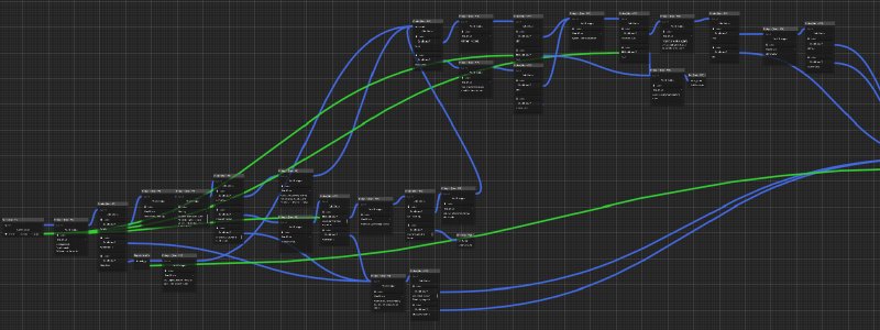
The most important point of this design is that it scales very well for large and branching dialogues. There is a clear visual way of showing which event or choice has influence on later choices or switches within the dialogue.
Conditionally Modifying Values
Many games have some kind of reputation system, which is often associated with some kind of integer value. In the following example we see, how the dialogue is able to conditionally modify such a value.

Here the dialogue receives the reputation, the player has, as an input for the start node. Based on the choice of the player, the reputation will be modified and the modified value (as well as the choice made) will be the output in the end node. Therefore, the dialogue receives data from the game and changes that data based on the logic of the dialogue. The writer of the dialogue encoded this logic. It wasn’t necessary to change the game’s code for this to work.
An important aspect to highlight is that, since the dialogue cannot contain loops, the operations can only be executed at most once. This makes the logic much easier to reason about, even for writers that have no programming knowledge. It is impossible to accidentally cause effects that are unaccounted for.

In the example above we have extended the example to also react to the reputation value and let the character give us an item if our reputation (after adding a constant to it) is high enough. Once again: This logic is fully integrated in the dialogue and does not live in the game’s code. The dialogue graph becomes a design document for the interaction of the player with the game’s characters, which is actually interpretable.

As show in the example above, we can also compute this reputation level on the fly based on completed quests given as input. The writer can freely decide the associated values and test those independent of the rest of the game. “Balancing” the dialogue and making creative decisions, when certain options become available, are self-contained.
Complex Skill Check
As a last example, let us look at a more complex skill check, that takes some skill, given as an integer value, and also balances the difficulty by checking if the check has been tried before. This example illustrates the “data-aware” aspect clearly.

I imagine that it would make for a fun experience to keep such checks hidden and therefore create a more natural conversation, where the outcome is not immediately obvious to the player.
Static Analysis
Something that I foresee as a major improvement to other dialogue editors is the possibility of static analysis on the graph. The term is borrowed from the field of program verification and refers to the method of analyzing properties of a program just by looking at its source code. This means that you don’t have to actually run the program to check certain properties on it.
Reachability Assertions
For the dialogue graph I imagine that to be very similar. Why should the dialogue writer need to execute the dialogue in order to test if a node is reachable? This should be done statically by the editor, by annotating nodes with their needed dependencies. Let’s look at an example:
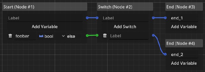
In this simple example we are interested in the reachability conditions for the two end nodes. Following their timeline connections backwards leads us to a switch node, which changes the timeline based on a data dependency. So let’s give the input of the switch node a unique name and write down the equations for it.
The first end can be reached if the switch input is false and the second end is reached if it is true, but what is the switch input? Following the dependency edge back, lets us arrive at the start node which associates a name with the boolean dependency, so now we can update the equations:
We could now annotate the nodes to show which variables have to be true in order to reach a node. This could help in keeping track of dependencies not just by visually inspecting the graph, but by getting detailed feedback on the relationship of data. Let’s look at another example:

Here things get slightly more complex, as we are dealing with an operation, aggregation and constant node. In the beginning our equations look the same:
However, now we need to update the equations with the operation node’s internal logic.
Furthermore, we have to account for the aggregation node, as the input for the operation node.
For the inputs of the aggregation node, we have a named boolean and a constant false.
And here we arrive at the insight that the first end node is impossible to reach, while the second end node will always be reached. This is something the editor can warn about since this does not seem to be intended. Particularly in large graphs these dependencies are not be obvious anymore, so this kind of analysis would help tremendously with large branching dialogues.
Integer Bounds & Randomness
This analysis also works for integers. Instead of talking about booleans and variables, we now have to extend our notion of equations with algebraic terms.

Here our previous equation will resolve to:
This also works with operations and constants. However, it makes the evaluation a bit more complicated as it has to allow for symbolic rewriting of the equations. While this is not impossible the logic becomes much more involved. Still, I believe this to be highly practical, as it can be used to analyze skill bounds for the reachability of certain nodes in the dialogue, helping the writer to reason about the flow and logical progressions within it.
An important aspect is also the random check. Assuming we are using a constant node in conjunction with a random check node, to achieve true randomness not dependent on any named parameters, we can precisely calculate the chance of a certain node to be reached.

For this we assume the random check to use a uniform random distribution from 1 to 10 inclusive.
Here we don’t compute a precise function to tell us about the reachability in “yes or no” terms, but in terms of probability.
Assuming there was a way to clamp the input values (by specifying a range of some kind), these calculations could be done for all integer bounds, giving the writer a detailed overview how likely certain outcomes in the dialogue are.
The Necessity of Being Loop-free
It turns out that this analysis will always work on our graph, as long as we can describe the dependency edges and timeline branching in logical terms. This is because each step in this analysis is a simple term-replacing and term-rewriting step for each node and equation the node is concerned with. Since there is only a finite amount of nodes to follow (until we hit a start or constant node), this analysis will always terminate with a result. This is a wonderful property to have, and it’s important to understand that it stems from the fact that the graph does not contain loops.
If our system allowed loops we would necessarily run into trouble, as we would need to compute loop-invariants for our equations, forcing us to generalize them until they hold for all loop iterations. This is impossible. Loops in conjunction with the check and operation nodes would allow us to construct functions that are equivalent to WHILE programs. As WHILE programs are equivalent to Turing machines we are necessarily running into Rice’s theorem which states that any non-trivial property of a Turing machine is undecidable. Therefore, it is necessary to exclude loops if we still want to keep check and operation nodes and make this kind of analysis possible.
In my last post I briefly mentioned that if loops were allowed, operations on data would need to be idempotent to not cause the same “effect” multiple times. Disallowing loops circumvents all of this additional complexity, that might cause unintended behavior.
Conclusion
I want to reflect on things that I think are good and bad about this system and how a real implementation might look like. Sadly, my proof-of-concept is poorly written, as I wasn’t familiar with Godot’s UI components and best-practices. Therefore, the code is currently in a buggy and unrefactorable state.2 Still, I believe that some important takeaways can be gathered.
Promising Results
In general, I believe the proposed system to be a fantastic tool for writers and game-designers to write more natural and more complex dialogues. Especially writers could benefit greatly from this system, as technical knowledge is not needed. In my opinion, the “data-aware” aspect of the system is exactly what is needed to create dynamic dialogues with manageable complexity.
Initially, I did not plan for the possibility of static analysis. It was something that I realized after starting work on the prototype. For the editor to be able to precisely show the writer which assertions have to hold for dialogue branches to become available seems like a real game-changer to me. It would allow the writer to use randomness to spice up the dialogues while still being able to easily reason about how likely every branch is.
On the technical side: It was a good idea to use Godot for the implementation of the editor. The possibility of exporting cross-platform builds with the possibility to host the application on the web is great. Being able to use the editor as a plugin within the Godot engine is also a big plus. Using JSON as an intermediate format was the right choice. JSON is easy to parse, easy to use in version control, and compresses well.3
A problem that has not been addressed yet, is how to store the data which is used as input and output for the dialogues. If we simply offload the need to store this data to the implementation of the game, we really haven’t achieved much. Do we still store everything as global data? Surely not. To fix this, I am imagining a system that allows to specify the data dependencies between dialogues the same way as describing the data dependencies within the dialogues. This would allow to implement a generic interface for storing data, which is handled by some kind of “meta-dialogue” system.
What Needs To Be Improved
It is not clear, how the dialogue can interact with the game it is embedded in. While I think it might be possible to react based on node labels, I don’t know if that really is a good system. There probably needs to be some kind of effect node that can be used to signal the start of an animation or a sound being played.
A problem that has not been addressed at all is how to handle unique IDs in a graph-based editor. Currently, every node simply contains the text that was entered in the GUI. There is no support for internationalization. To do this, text (which is displayed to the player) needs to have some kind of unique ID. However, this raises a few questions. How can we move a dialogue text from one dialogue node to another? We can’t just simply copy and paste the text, as the IDs wouldn’t match and internationalization would break if it relies on them. There needs to be some clever system invented here.
While the prospect of static analysis is very promising, the systems needs a clearer mathematical specification akin to denotational semantics for the nodes in the system. This is also a requirement for making sure that other developers are able to implement interpreters for the dialogues for their engines.
This is just a Programming Language, isn’t it?
As was described in the beginning of this post, dialogues are basically functions. If we assume that there is only one start and one end node and ignore the label input and output of the function we are left with a function from one map of variables to another. We can further simplify by assuming that there is only a single result value. Then we have:
That’s just a boring old function we can define in any programming language! As the previous discussion shows, if we allow loops this system can simulate any computable function. So, essentially this whole system is just a graph-based programming language. But then, how do the choice and dialogue nodes fit into the picture?
If our data dependencies and the nodes working with them are enough to program with them, what are the other nodes (that seemingly only consume data, but don’t modify or produce it) doing? Since they are signaling to the interpreter that something outside the computed function should happen, we are dealing with a side effect! The only reason we need the timeline edges at all is because we need some way to specify the order of effects, as the evaluation of values is call-by-need.
Funnily, enough this is very similar to how Haskell evaluates its values and effects.
While values are call-by-need by default, effects need to be ordered.
This is done using monadic programming.
However, this alone wouldn’t fix the fact that evaluations are call-by-need.
To order the execution of effects, the function to “bind” the effectful IO monad has to thread a special value of type RealWorld through the monadic computation.
This forces the compiler to not reorder the execution of effects!
See the bindIO function for more detail.
In the dialogue system, this is done by threading timeline edges through the nodes. This came up before in the discussion of the necessity of timeline connections for the check node.
I am almost not shocked about this result. To a certain degree, it makes perfect sense, that this system is just a programming language, as it deals with variables, operations on variables, and sequencing of effects. However, I have this weird feeling that something about this system is wrong. Is it really just programming without loops? To me there are two ways to look at it:
- This system does too much: All I wanted, was to show some dialogues in a video game and give the player a chance to react to it. Is all of this data-wrangling really necessary? Maybe the system should be cut down, simplified and streamlined such that all of this complexity can be thrown out. Data from events (which we modeled with the flag node) could be made implicitly known. Computing with integers could be thrown out entirely. Maybe this would make for a simpler system.
- This system isn’t powerful enough: Why restrict ourselves? This clearly isn’t just a dialogue system. Why wouldn’t this system need to be confined to the role of a single, simple system within the whole game? The system could fully take over the whole logic of the video game. It can handle computations and effects, so there is no obvious reason why this shouldn’t work. This way, game programming would become visual, simple and available to anyone!
I’ll let you decide which idea you agree with. Anyway, I think, I’ll leave the design of dialogue systems to game designers; I am clearly not smart enough to figure this out.
-
The scenario I wanted to avoid is the system used in the fantastic game Scarlet Hollow which reportedly uses 500-1000 distinct booleans to flag events that happened in less than half of the full story. ↩︎
-
Only after implementing most of the editor’s control flow did I attempt to implement undo-redo using the UndoRedo class. Sadly, it’s almost impossible to retrofit my old code to fit, so fixing this would constitute a partial rewrite anyways. ↩︎
-
A pretty short test dialogue with a size of ~16KB can be compressed down to ~2KB using LZMA2. The size of the JSON representation is a bit too large for my liking, since it doesn’t lend itself well to represent graph structures. This requires a lot of redundant information to reference nodes in multiple places. This is where compression helps greatly. ↩︎